ZACUBE-1 (South Africa CubeSat-1) / TshepisoSat
ZACUBE-1 is a student-developed CubeSat of CPUT (Cape Peninsula University of Technology), Cape Town, South Africa. Development of ZACUBE-1 commenced in early 2011. Its main payload is a high frequency (HF) beacon transmitter that will be used to help characterize the Earth’s ionosphere and to calibrate SANSA’s (South African National Space Agency) auroral radar installation at the SANAE¿IV base in Antarctica. ZACUBE-1’s ADCS was developed in a collaboration between F’SATI and ESL (Electronic System’s Laboratory) at Stellenbosch University, Stellenbosch, South Africa.
The F’SATI (French South African Institute of Technology ) at CPUT offers a postgraduate Satellite Systems Engineering Program. The program was established to develop human capacity in support of the South African government’s endeavor to develop Science, Engineering and Technology (SET) industries in the country. F’SATI is mainly government funded through the NRF (National Research Foundation).

The ZACUBE-1 satellite has been renamed to TshepisoSat, after a competition held for Grade 9 learners. Tshepiso is the Sotho word meaning “promise”.
Spacecraft
The CubeSat standard and platform is used as research vehicle. A Pumpkin kit along with a MSP430-based OBC (On-Board Computer) was purchased from Pumpkin Inc. The 1U CubeSat has a mass of 1.2 kg.
ADCS (Attitude Determination and Control Subsystem): The ADCS was developed in-house by F’SATI’s development team in collaboration with ESL at Stellenbosch University. ADCS uses X- and Y- axis magnetorquer rods and 3-axis magnetorquer coils that are included in the Clyde Space solar panels. A three axis magnetometer device is included on the ADCS module and an additional three axis magnetometer can be deployed from the satellite on a 5 cm stalk for improved measurement sensitivity.
The ADCS control algorithm was developed by the team of students at Stellenbosch University and implemented in an on-board Atmel microprocessor. A BDOT magnetic controller is used to zero the X and Z body rates and a magnetic Y-spin controller forces the Y body rate to follow a reference. A Kalman rate filter, which only uses magnetic field measurements, is implemented to estimate Y body rates that are used by the Y-spin controller.

EPS: Electrical Power Subsystem): The EPS uses a lithium polymer battery module and five body mounted solar panels incorporating magnetorquer coils, all from Clyde Space.
RF communications: Telecommand and telemetry communication is established with ZACUBE-1 via a VHF uplink (145.86 MHz) and a UHF downlink at 437.345 MHz. Both links operate in the amateur bands at selectable transmission rates of 1.2 kbit/s or 9.6 k bit/s. The communications transceiver was also developed in-house. The prototypes of a UHF receiver and UHF transmitter circuitry from two MTech (Master of Technology) thesis projects were adapted and developed into flight hardware by F’SATI’s development team. The transceiver uses a deployable VHF / UHF antenna module of ISIS (Innovative Solutions in Space) BV, Delft, The Netherlands.


Launch: ZACUBE-1 was launched on Nov. 21, 2013 as a secondary payload on a Dnepr vehicle from the Dombarovsky (Yasny Cosmodrome) launch site in Russia. The primary payloads on this flight were: DubaiSat-2 of EIAST (mass < 300 kg) and the STSat-3 minisatellite of KARI, Korea (~150 kg). 8) 9) 10) 11) 12)
The secondary payloads on this flight were:
• SkySat-1 of Skybox Imaging Inc., Mountain View, CA, USA, a commercial remote sensing microsatellite of ~100 kg.
• WNISat-1 (Weathernews Inc. Satellite-1), a nanosatellite (10 kg) of Axelspace, Tokyo, Japan.
• BRITE-PL-1, a nanosatellite (7 kg) of SRC/PAS (Space Research Center/ Polish Academy of Sciences of Warsaw, Poland.
• AprizeSat-7 and AprizeSat-8, nanosatellites of AprizeSat. AprizeSat-7 and 8 are the ninth and tenth satellites launched as part of the AprizeSat constellation, operated by AprizeSat. The constellation, which was originally named LatinSat, was initially operated by Aprize Argentina; however ownership of the constellation was later transferred to their US parent company AprizeSat. The AprizeSat constellation is used for store-dump communications, and some satellites carry AIS (Automatic Identification System) payloads for Canadian company ExactEarth. The AprizeSat spacecraft were built by SpaceQuest Ltd. Of Fairfax, VA, USA, and each has a mass of 12 kg. 13)
• UniSat-5, a microsatellite of the University of Rome (Universita di Roma “La Sapienza”, Scuola di Ingegneria Aerospaziale). The microsatellite has a mass of 28 kg and a size of 50 cm x 50 cm x 50 cm. When on orbit, UniSat-5 will deploy the following satellites with 2 PEPPODs (Planted Elementary Platform for Picosatellite Orbital Deployer) of GAUSS:
– PEPPOD 1: ICube-1, a CubeSat of PIST (Pakistan Institute of Space Technology), Islamabad, Pakistan; HumSat-D (Humanitarian Satellite Network-Demonstrator), a CubeSat of the University of Vigo, Spain; PUCPSat-1 (Pontificia Universidad Católica del Perú-Satellite), a 1U CubeSat of INRAS (Institute for Radio Astronomy), Lima, Peru; Note: PUCPSat-1 intends to subsequently release a further satellite Pocket-PUCP) when deployed on orbit. 14)
– PEPPOD 2: Dove-4, a 3U CubeSats of Cosmogia Inc., Sunnyvale, CA, USA
MRFOD (Morehead-Roma FemtoSat Orbital Deployer) of MSU (Morehead State University) is a further deployer system on UniSat-5 which will deploy the following femtosats:
– Eagle-1 (BeakerSat), a 1.5U PocketQub, and Eagle-2 ($50SAT) a 2.5U PocketQube, these are two FemtoSats of MSU (Morehead State University) and Kentucky Space; Wren, a FemoSat (1U PocketQube) of StaDoKo UG, Aachen, Germany; and QBSout-1S, a 2.5U PocketQube (400 g) of the University of Maryland testing a finely pointing sun sensor.
• Delfi-n3Xt, a nanosatellite (3.5 kg) of TU Delft (Delft University of Technology), The Netherlands.
• Triton-1 nanosatellite (3U CubeSat) of ISIS-BV, The Netherlands
• CINEMA-2 (KHUSat-1) and CINEMA-3 (KHUSat-2), nanosatellites (4 kg each) developed by KHU (Kyung Hee University), Seoul, Korea for the TRIO-CINEMA constellation. TRIO-CINEMA is a collaboration of UCB (University of California, Berkeley) and KHU.
• GOMX-1, a 2U CubeSat of GomSpace ApS of Aalborg, Denmark
• NEE-02 Krysaor, a CubeSat of EXA (Ecuadorian Civilian Space Agency)
• FUNCube-1, a CubeSat of AMSAT UK.
• HiNCube (Hogskolen i Narvik CubeSat), a CubeSat of NUC (Narvik University College), Narvik, Norway.
• ZACUBE-1 (South Africa CubeSat-1) and after launch renamed to TshepisoSat, a 1U CubeSat (1.2 kg) of CPUT (Cape Peninsula University of Technology), Cape Town, South Africa. 15)
• UWE-3, a CubeSat of the University of Würzburg, Germany. Test of an active ADCS for CubeSats.
• First-MOVE (Munich Orbital Verification Experiment), a CubeSat of TUM (Technische Universität München), Germany.
• Velox-P2, a 1U CubeSat of NTU (Nanyang Technological University), Singapore.
• OPTOS (Optical nanosatellite), a 3U CubeSat of INTA (Instituto Nacional de Tecnica Aerospacial), the Spanish Space Agency, Madrid.
• Dove-3, a 3U CubeSats of Cosmogia Inc., Sunnyvale, CA, USA
• CubeBug-2, a 2U amateur radio CubeSat of Argentina (sponsored by the Argentinian Ministry of Science, Technology and Productive Innovation) which will serve as a demonstrator for a new CubeSat platform design.
• BPA-3 (Blok Perspektivnoy Avioniki-3) — or Advanced Avionics Unit-3) of Hartron-Arkos, Ukraine.
Deployment of CubeSats: Use of 9 ISIPODs of ISIS, 3 XPODs of UTIAS/SFL, 2 PEPPODs of GAUSS, and 1 MRFOD of MSU.
Orbit: Sun-synchronous near-circular orbit, altitude = 600 km, inclination = 97.8º, LTDN (Local Time on Descending Node) = 10:30 hours.
Mission status:
• March 10, 2014: The CubeSat of CPUT is in the commissioning phase, the attitude control is still in free tumble. 16)
• On March 5, 2014, ZACUBE-1 came within an estimated 185 m of the defunct Russian COSMOS 2151 satellite over Antarctica. The second warning was received on March 6, with ZACUBE-1 predicted to come within 85 m of yet another defunct Russian satellite, METEOR 2-5, over Brazil. However, without a propulsion control, there is nothing that can be done to alter the course or altitude of ZACUBE-1. 17)
• First signals of ZACUBE-1 were received.
Sensor complement: (HF beacon antenna, Camera)
The satellite’s main payload is a HF (High Frequency) beacon transmitter that will be used for research in the geospace environment. Research and development of the payload and supporting ground station systems is done in collaboration with the Space Science Directorate of SANSA (South African National Space Agency). The main objective of the HF Beacon on ZACUBE-1 is to provide a continuous radio signal to determine the elevation resolving algorithm of the SuperDARN HF Radar antenna at SANAE in Antarctica. The signal will also be used to characterize the beam pattern of this and other HF Radar antennas in the SuperDARN network, and to characterize the ionosphere over the polar regions. 18)
The HF beacon transmitter operates at a radio frequency of 14.099 MHz and transmits up to 200 mW of RF power. The carrier is ASK modulated with a Morse code message; the data rate is up to 60 bit/s.
Objectives:
The first objective of the mission is to independently measure the elevation angle of the incoming signal from the satellite on the ground and to compare it with the results of other methods currently used by SANSA Space Science. An interferometer receiver array installation will be constructed at SANSA Space Science in Hermanus, South Africa where there is also an ionosonde which can be used to characterize the bottom side ionosphere. Several dual frequency GPS receivers are also available at and near Hermanus which can be used for finding the electron density via ionospheric tomography. The data from both the ionosonde and the dual frequency GPS receivers will be used to tune and improve the accuracy of the IRI (International Reference Ionosphere) model for the ionospheric electron density, which will be used for ray tracing from the satellite to the receiver. Having calculated the diffracted ray path as accurately as possible, it can then be compared with the known angle to the satellite to deduce the angle of diffraction for the specific path through the ionosphere. This information can then be used to calibrate the interferometer array.
A second objective is to use the HF beacon signal to ultimately characterize the beam pattern of the TTFD (Twin Terminated Folded Dipole) antenna array of SANSA’s HF radar in Antarctica and to enable the extraction of accurate elevation angle measurements using the radar’s interferometer array, which is located 100 m north of the main array. The radar is located at SANAE-IV, the South African Polar Research Base in Antarctica (Figure 8) and forms part of an international network known as the SuperDARN (Super Dual Auroral Radar Network) which monitors the ionosphere’s electron density and movement.

Legend to Figure 5: SANAE, the South African Polar Research Base in Antarctica, is located at 2.84ºW, 71.67ºS.
A limitation of using the HF beacon on the satellite for the characterization of the antenna at SANAE-IV is that the ionosphere will refract the signal from a LEO (Low Earth Orbit) satellite. Hence the location of the satellite relative to the receiver will not be sufficient for finding the elevation angle. The actual angle of incidence after refraction through the ionosphere can be determined by ray tracing, which requires information about the electron density in the ionosphere along the ray path. Once the interferometer array at Hermanus is characterized and calibrated, it can be applied to the HF radar antenna at SANAE-IV, where there is no ionosonde, and therefore in an area where the electron density of the ionosphere is unknown. The incoming signal’s elevation angle can be compared with the ray traced results, in order to adjust the IRI (International Reference Ionosphere) model for the ionospheric electron density.
Deployable HF beacon antenna:
To radiate the HF signal efficiently, an antenna aperture of half a wavelength is required, i.e. approximately 10 m at 14 MHz. The simplest concept of a wire antenna was adopted. A flexible cable rope was selected as the element and a small tip mass was attached to the open end. The satellite will be placed in a constant Y-Thomson spin so that the centrifugal force will keep the wire extended.
A specialized deployment mechanism was developed to stow the antenna inside ZACUBE-1 during launch. The cable is coiled onto a bearing mounted reel and during deployment an electric motor and gearbox assembly pulls the wire out of the satellite, uncoiling the reel.

VGA Matrix Camera
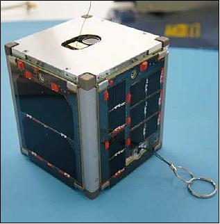
A VGA matrix camera is included as a secondary payload. The camera looks along the axis of the HF antenna and can be used to monitor deployment. The camera’s lens can be seen in Figures 1 and 7 in the opening on ZACUBE-1’s top surface next to the HF antenna tip mass.

SANAE IV (South African National Antarctic Expedition IV)
SANAE IV is located at Vesleskarvet in the Queen Maud Land region of Eastern or Greater Antarctica (71°40′ 22”S 2°50’26”W), at an elevation of 856 m. The base is on top of a distinctive flat-topped nunatak, Vesleskarvet, on the fringe of the Ahlmann Range of mountains. The base is approximately 80 km from the edge of the continent (also known as the grounding line or hinge zone) and 160 km from the edge of the ice shelf. Vesleskarvet is completely surrounded by the glacial ice sheet.
Several unsuccessful attempts have been made before to calibrate the interferometer of the SuperDARN antenna array at the SANAE base in Antarctica which is used for sensing the dynamics of the ionosphere over Antarctica. The attempts included the transmission of HF signals from a helicopter which failed due to the intermittent nature of the transmissions. Continuous HF radio transmission from a satellite in LEO (Low Earth Orbit) was proposed as a viable alternative for the calibration of the SuperDARN radar.
SuperDARN (Super Dual Auroral Radar Network) is an international network of radars which are being used for monitoring the plasma convection in Antarctica and in the Arctic region. Presently, there are fourteen SuperDARN radars in the northern hemisphere and eight in the southern hemisphere with operating frequencies in the range 8-20 MHz. These radars are almost identical in design and each of them transmits a short sequence of pulses in the HF band and samples the returning signals. These radars are capable of measuring the position and velocity of charged particles in the Earth’s ionosphere. For over ten years now, data from the SuperDARN radars has proven to be extremely useful in addressing a wide range of scientific questions concerning processes in the magnetosphere, ionosphere, thermosphere, mesosphere and general plasma physics. 19) The HF Radar at SANAE is one of the first SuperDARN radars to be deployed in the Earth’s polar region.

Ground Segment
The ground segment of the mission includes a tracking, telemetry, and control (TT&C) station at CPUT and a direction finding (DF) array designed to determine the angle of arrival of the HF beacon signal in both azimuth and elevation. The DF array will initially be deployed at SANSA in Hermanus, and then at SANAE. An HF direction finding system is also available at Grintek Ewation in Pretoria. Figure 9 shows the locations of the DF arrays.

Source: https://earth.esa.int/web/eoportal/satellite-missions/v-w-x-y-z/zacube-1
admin
Vivamus in erat ut urna cursus vestibulum. Fusce commodo aliquam arcu. Nam commodo suscipit quam. Quisque id odio. Praesent venenatis metus at tortor pulvinar varius.Lorem ipsum dolor sit amet, consectetuer adipiscing elit. Aenean commodo ligula eget dolor. Aenean massa. Cum
Arlando Viva
Aenean quis sem ut justo euismod porttitor. Praesent vel magna at massa lacinia malesuada id id sem. Nulla egestas imperdiet commodo. Nunc egestas nisl eu quam mattis suscipit. Maecenas iaculis, felis eu ultricies posuere, sapien sem eleifend erat, non tincidunt purus velit eu odio. Duis feugiat eros eu turpis bibendum, at lobortis quam consequat.
Mila Koss
Lorem ipsum dolor sit amet, consectetur adipiscing elit. Quisque sit amet venenatis orci, ut tempus ipsum. Donec sit amet massa et dui ultricies eleifend. Curabitur at nibh ante. Mauris vulputate massa quis nisl eleifend, in pellentesque felis convallis. Ut quis consectetur turpis, vel dictum risus. Quisque venenatis nisi sed magna pharetra, non tincidunt ante laoreet. Sed cursus tellus ut cursus tristique.
Paul Donavane
Fusce a quam. Etiam ut purus mattis mauris sodales aliquam. Curabitur nisi. Quisque malesuada placerat nisl. Nam ipsum risus, rutrum vitae, vestibulum eu, molestie vel, lacus. Augue ipsum, egestas nec, vestibulum et, malesuada adipiscing, dui. Vestibulum facilisis, purus nec pulvinar iaculis, ligula mi congue nunc, vitae euismod ligula urna in
Paul Donavane
Nunc egestas nisl eu quam mattis suscipit. Maecenas iaculis, felis eu ultricies posuere, sapien sem eleifend erat, non tincidunt purus velit eu odio. Duis feugiat eros eu turpis bibendum, at lobortis quam consequat.